G'day guys!
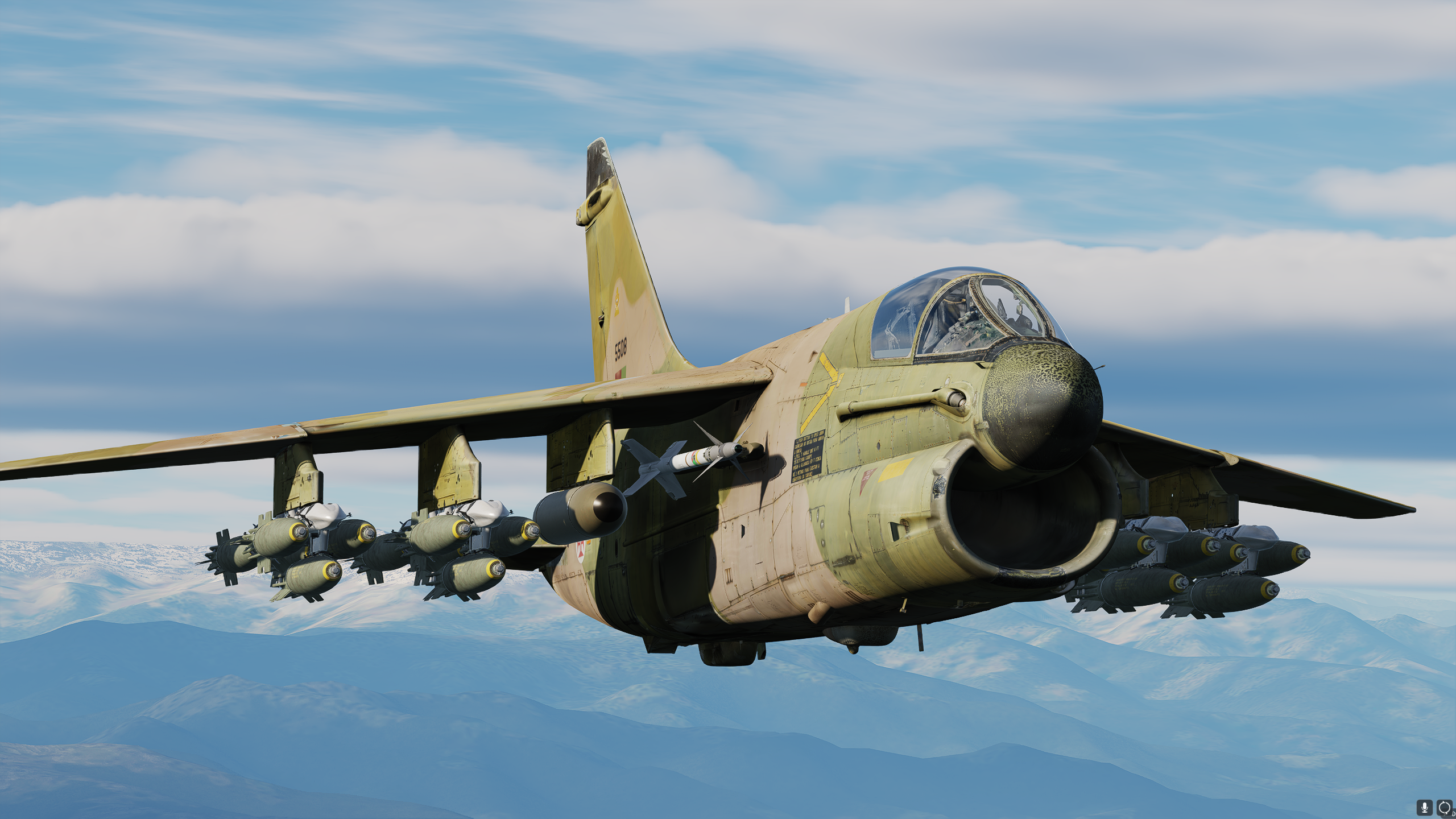
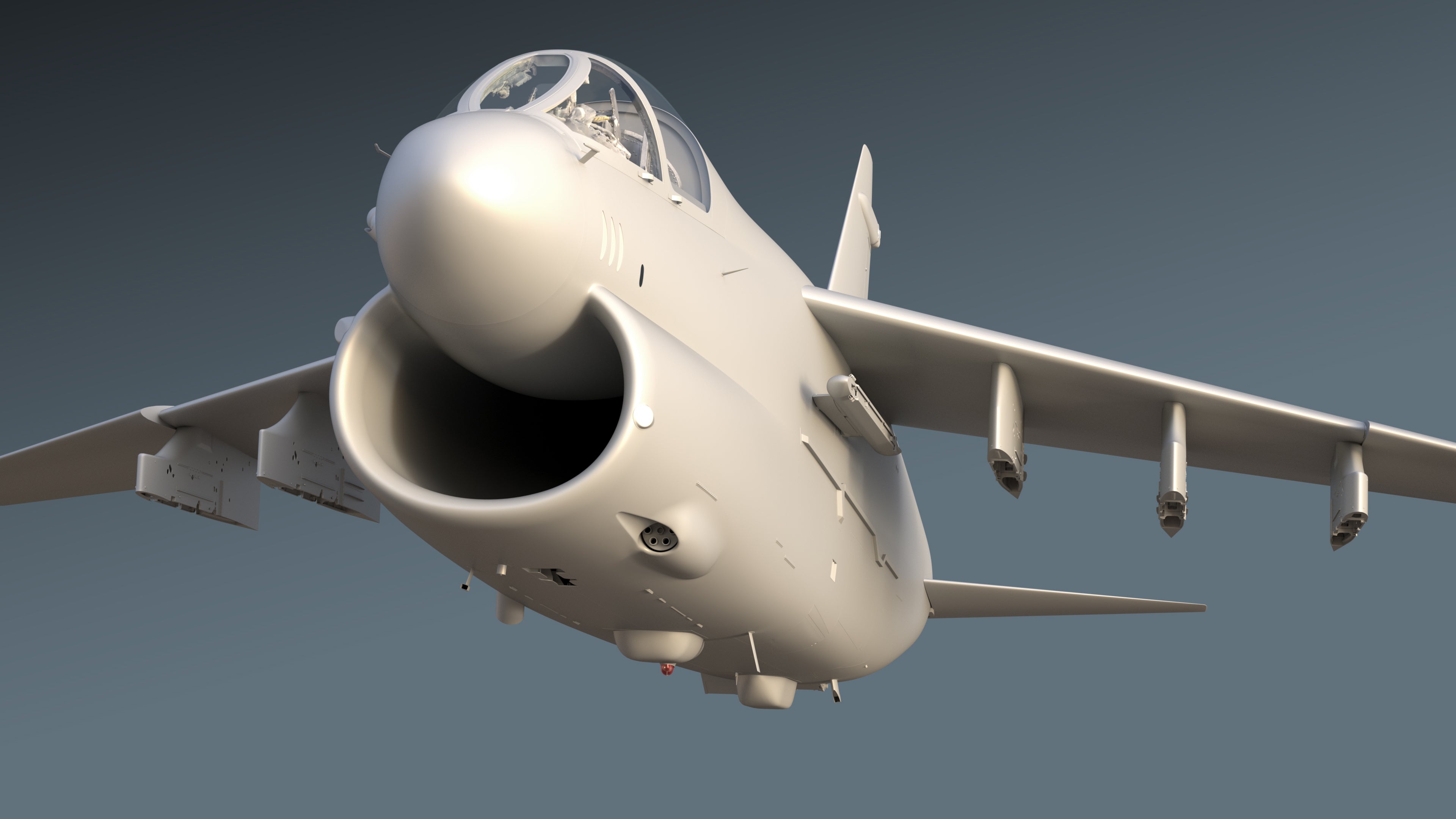
We know that you've been itching to find out more, so this report will be purely focused on the development state of the A-7E Corsair II for DCS World. The SLUF has an all new, much improved 3D model and today we're happy to be sharing the first pictures of the new model in-sim!
First, I must apologize for the lengthy gap between development updates. We understand that many of you are keen for more regular update reports, and I will strive to do my best going forward to try and keep the development news flowing through more regularly.
Without further ado, let's dive into what we've been up to in 2023!
ARTWORK
2023 has been a wild ride for our beloved Corsair; with some difficult decisions being made throughout the year. In our previous report, we unveiled our overhauled and remade 3D model in all of its beauty. The model was exquisitely detailed, and we were very proud of it (and still are) - especially considering the model was built from only photos and blueprints.
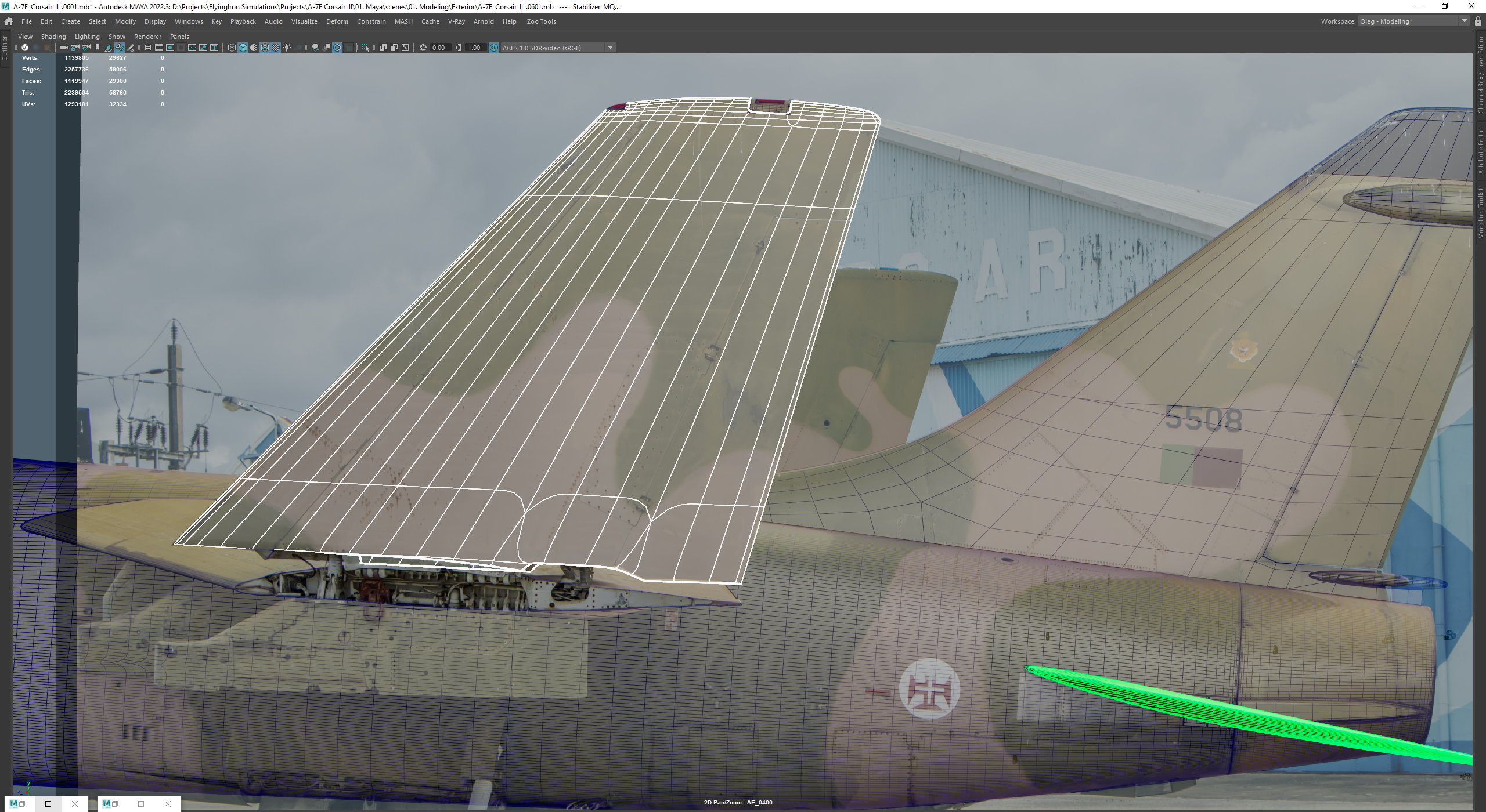
In 2023, we recruited a new artist, Oleg, who is a veteran of the industry & aircraft modelling, having worked previously with some of the very best teams in Flight Simulation. Not only an incredible 3D artist, Oleg has extensive experience with photogrammetry; the fascinating process of extracting a 3D model from a real-world object via a detailed photography process.
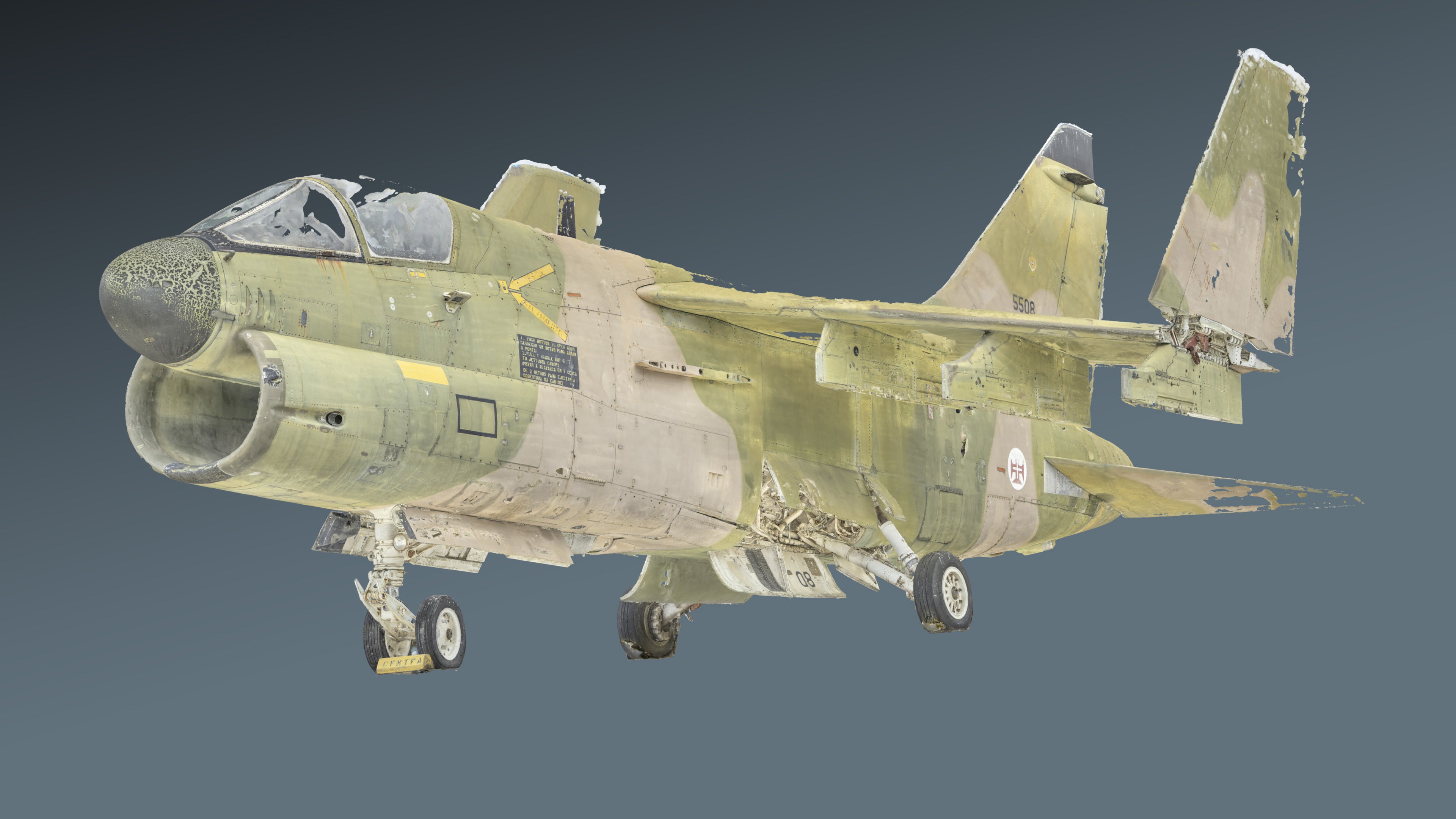
This presented us with a unique opportunity to do something we've never done before - scan an entire aircraft as the basis of our model. After being presented with this opportunity, we made the very difficult decision to remake the 3D model AGAIN. Now I know what you're thinking, and don't worry - this decision hasn't had any effect on our release projections; there is still plenty of more programming work to be done in tandem. Of course, this decision was very painful for us, having to set aside thousands of hours of work is not a decision to be made lightly.
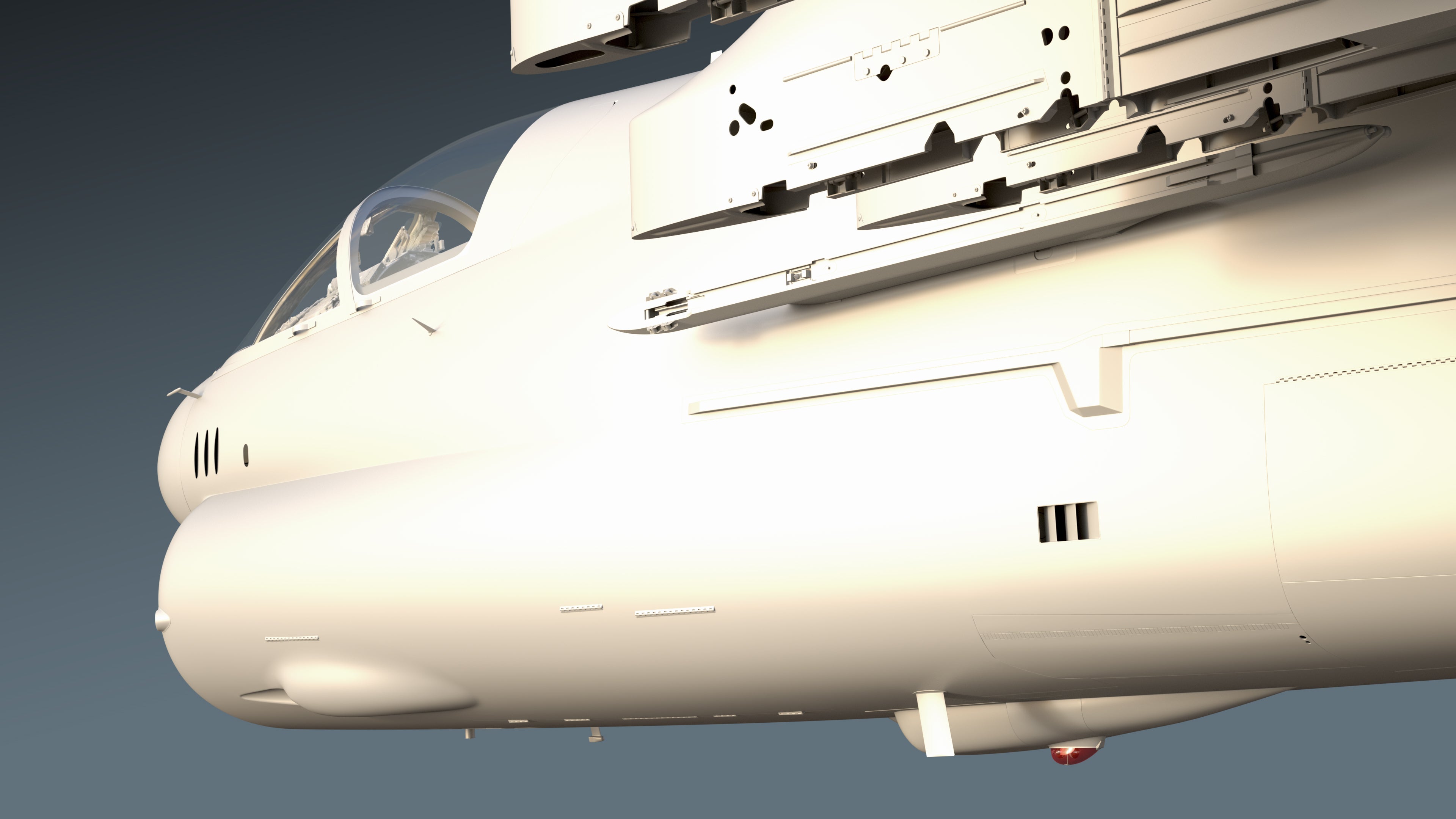
Ultimately though, we believe that this was the best decision going forward for the team, for the module and for the consumer. Our previous model was excellent, however any model built from blueprints & photos is prone to inaccuracies, as minor as they may be. This is just the nature of dealing with wild blueprint inaccuracies, incomplete photo reference and managing strange photo perspectives and alignment. Photogrammetry eliminates these errors and inaccuracies, providing a true-to-life 3D reference of the model and textures.
The external model has progressed at an incredible pace thanks to the photogrammetry, and soon work will begin on the cockpit remodel.
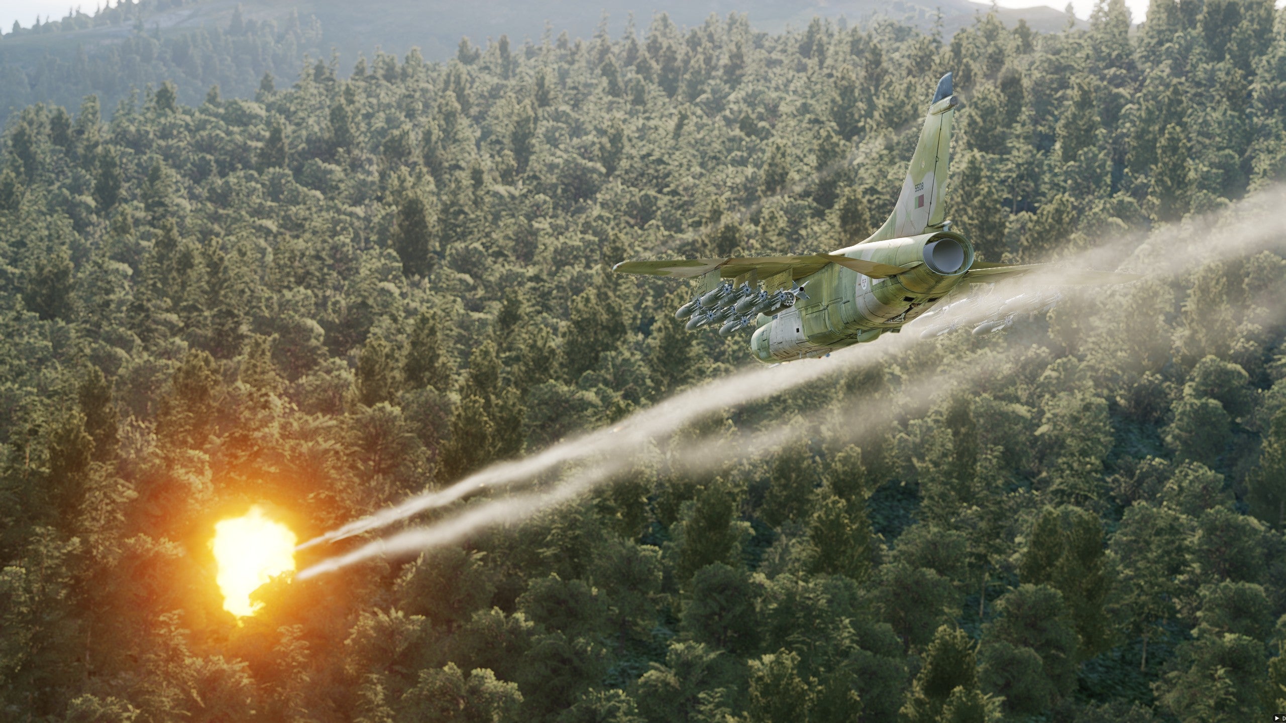
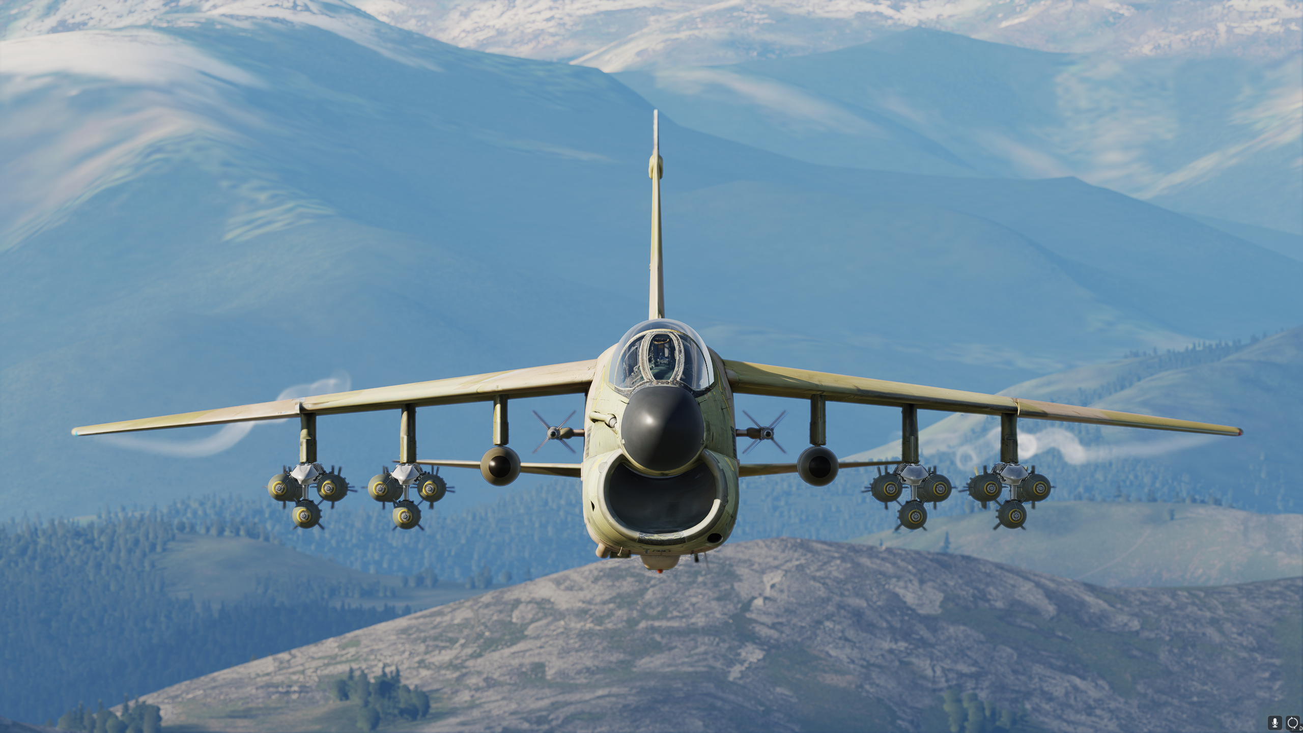
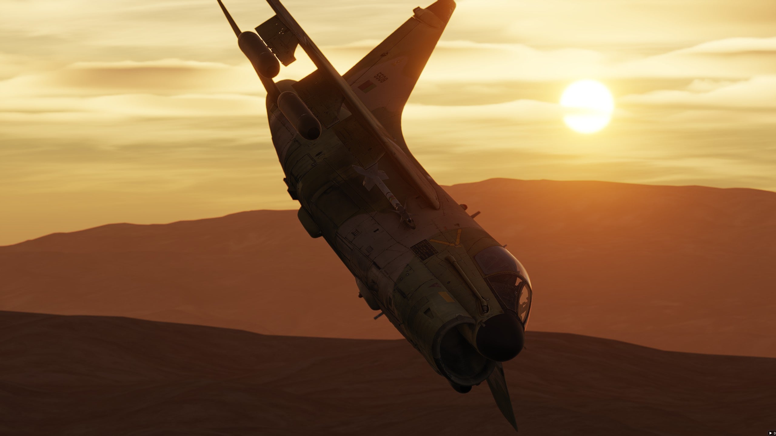
Now that the new model has been in development for some time, we are absolutely confident that we made the right decision, and we think that these screenshots might just convince you too ;)
Note that the textures here are using the scan reprojection from an A-7P, and don't necessarily represent the final textures or level of wear & tear.



PORTUGAL TRIP
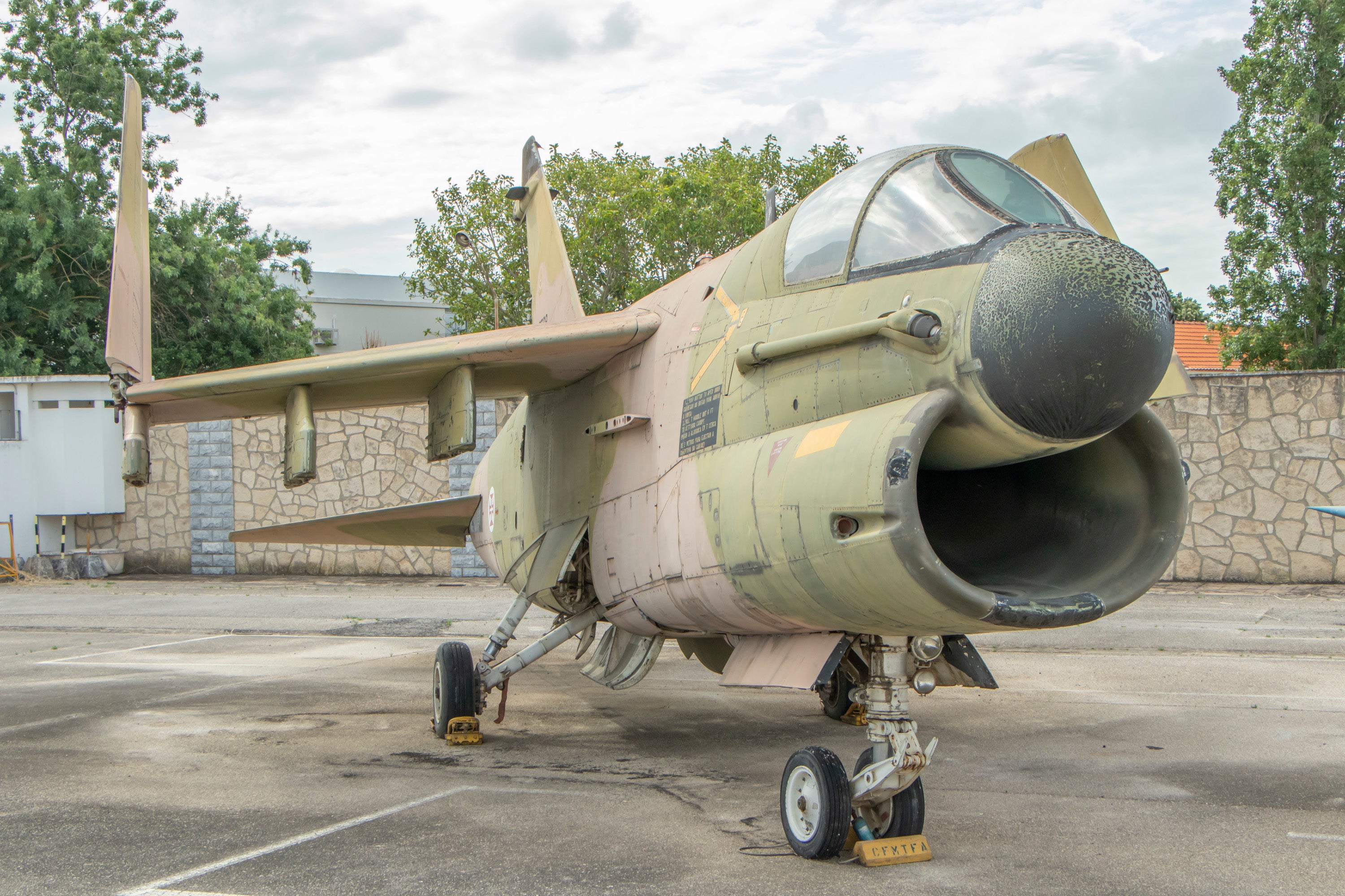
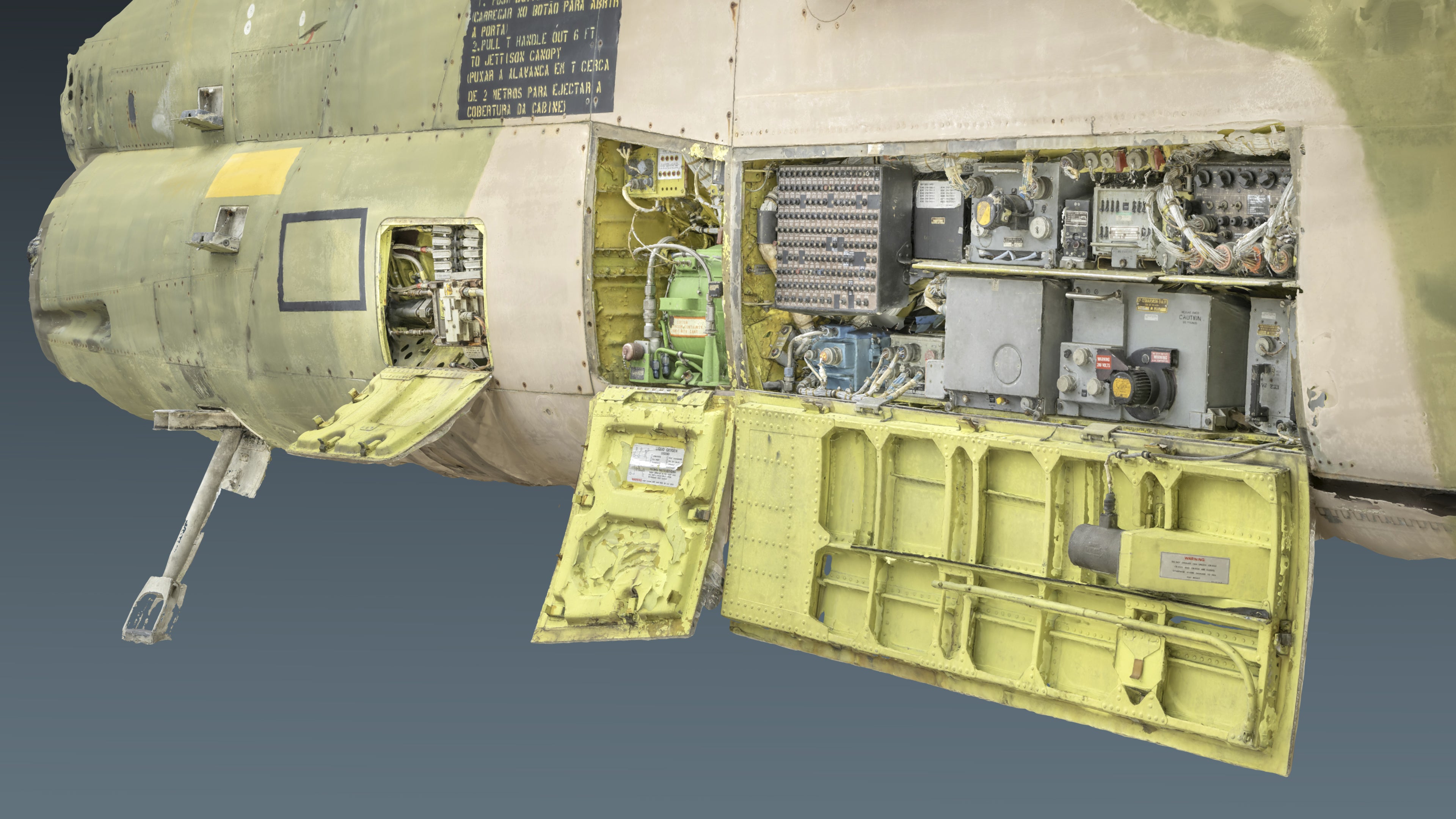
Earlier this year, Oleg & all of his gear packed up and made the journey to the Museu do Ar (Air Museum) in Portugal. The museum is home to 2 beautiful A-7P aircraft - one in Ovar, and one in Alverca (plus an additional cockpit display in Sintra). We were lucky enough to be granted full access to both aircraft; not only the exterior and cockpits, but also to internals such as the radar & avionics bays, landing gear compartments and intake!
With perfect weather shining down on our scanning days, we were able to capture near perfect scans of both airframes - giving us not only 1, but 2 complete reference models. This took several days of laborious photography, crawling inside tiny compartments, setting up lighting rigs and capturing tens of thousands of photos from every angle imaginable. As you can see, the end result has been well worth the effort. We are immensely proud of the new artwork and the progress it's been making; Oleg is doing fantastic work and we truly believe it will be up there with some of the best in DCS World.
Of course, we didn't stop there - you don't get an opportunity like this every day! We also used the opportunity to capture video footage inside the cockpit, providing detailed reference of switch, dial and lever motions to provide accurate reference for animation. The final step, using a professional microphone rig, was to capture all of the unique cockpit sounds that we possibly could. Although it would be very easy to use generic switch & lever sounds, we think using genuine sounds from the real cockpit just adds that extra level of immersion & authenticity.


FLIGHT MODEL
Moving into Phase 4
In the last few months, work has been mainly focused on further developing and refining the flight model, with the aim of getting it ready for testing and into phase 4 of development. It's been quite a lengthy process, requiring a redevelopment of the equations driving the flight model, in order to be able to better integrate the CFD data we have been capturing. We also came across a new source of wind-tunnel data this year, providing more direct data to be used in our tables as well as providing very useful validation data for our CFD model.
Without getting too technical, we have significantly expanded upon our stability & control derivative modelling, replacing previously linear derivatives with complete non-linear data tables, often with 3 or 4 dependencies and inputs. Again, this goes above & beyond the derivatives provided from wind-tunnel testing and provides a more in-depth and accurate simulation of aircraft dynamics, particularly at & beyond the edge of performance envelope.
This year also saw the expansion and development of the TF-41 engine simulation, with much the same process being applied here. Various data reports & engine simulation software were used to create a comprehensive picture of engine performance, with work ongoing to further develop simulations of various engine subsystems & quirks. The TF-41 is a relatively slow engine to respond, adding an even greater challenge to carrier landings and Air Refuelling operations.
Finally, 2023 has seen the completion of the Automatic Flight Control System (AFCS), which includes a complete Control Augmentation System (CAS) as well as multiple autopilot operating modes. We've previously discussed the AFCS in detail and the importance it has on all areas of flight - we're now happy to report that it is finished and awaiting testing!
Optimization & Efficiency
An EFM in DCS World is typically simulated every 0.005 seconds - meaning that the flight model is updated & recalculated 200 times every second. This is necessary to allow for the accurate computation of aerodynamic models and also for accurate reading of pilot inputs, providing an appropriate level of sensitivity and resolution. Given that an aerodynamic model consists of huge amounts of data (often thousands of data points split into as many as 100+ tables) and heavy calculations, any inefficiencies in the EFM model can lead to a degradation in performance at all times in flight.
For this reason, we have been spending time optimizing and improving runtime efficiency in our flight model to try and ensure we have the best possible performance. The focus here was to redevelop our Look-up Table (LUT) model from the ground up, using the latest available research to help direct our efforts.
Without getting too far into the nitty gritty details, we have been able to significantly improve the processing time of a simulation loop by increasing the speed & efficiency of our look-up tables. Typically in a LUT, data is stored in tables, which usually have up to 20-30 rows and often the same amount of columns. The computer will take an input, such as AoA, and loop through the table until it finds the nearest matching values. From there we can do mathematical interpolation to determine the correct value that matches our input. This is repeated for each table (can be 100+ tables), and the whole process repeated 200 times per second.
While this is an acceptable process in most cases, there is certainly room for improvement. One such approach is to store the previous result, and then use that as a starting to place for the next search loop through the data table. This helps, but still requires a full search loop whenever a large change in input occurs. Our new LUT model however does not require any searching or loops; instead, we have developed a clever method that involves manipulating our data sets so as to maintain a linear relationship between inputs & corresponding data tables, so that the table index (or where to look in the table) can be simply computed from the table input value.
We have of course expanded the model to include n-dimension tables, so that it is ready to handle any fresh CFD data we can throw at it! It was important for us to get this right, not only for the performance reasons above but also because the LUT model is a cornerstone of the EFM, and can be reused in any future modules.
CFD WORK
You'd be forgiven that we would be finished with CFD work on the A7 by now, but not quite! Previously, our CFD model was built in NASA's OpenVSP software, meant to only be a crude representation of the A7 with a very simple, performance based mesh. This has given us acceptable results over the last year, most of which has been implemented into the Flight Model already.
However, having captured the scans on a real A7, the opportunity to collect fresh & more accurate CFD data was suddenly available. So this year, using the scan as a base, we have been busy also rebuilding our CFD mesh; this time using a much more detailed and accurate mesh. Given that CFD is entirely mesh dependant, an upgrade to mesh fidelity consequently provides an increased data resolution and accuracy. This was particularly beneficial for capturing peripheral data that is not present in the literature, such as landing gear forces, speedbrake forces and so on. Our previous mesh was very simplistic, and thus only captured a general idea of the forces. Now however, we are building our CFD mesh from Oleg's incredible scanning and modelling work, providing 1:1 accuracy with the mesh and consequently the data collected.
It has been a difficult & intensive process, as anyone that has worked in CFD can undoubtedly attest to. Fortunately, we have been working closely with Research in Flight once again to further refine our new model and ensure validity of our collected data. It is a large undertaking and fairly heavy workload, however we are grateful to have the opportunity to work with the experts to really develop our CFD knowledge & skills; not only is it a huge benefit to the A7, but it also opens the door for us to be able to model any future aircraft with full EFM fidelity.
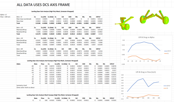
Here you can see just a very, very small sample of some of data collected from a test run of the landing gear model.
MECHANICAL SYSTEMS
The Corsair has a beautiful duality as an aircraft; it was a technological pioneer of the time, featuring the first fully-fledged Heads-Up Display unit that we are so familiar with in modern aircraft. Yet, it was also very much an 'analogue' jet of the past, lacking the huge array of sensors and digital control systems that modern fighters are equipped with. The Corsair is a very much a hybrid of the two; a transition between two eras in military aviation.
With this in mind, we've been spending some more time this year really expanding upon our simulations of the aircrafts mechanical systems such as gear & ground operations, carrier ops & systems, hydraulic & fuel systems. While these aren't as flashy as the weapons & avionics systems, these elements make up a considerable portion of the airframe, procedures and overall simulation experience, and its important that we get them right.
As a simple example, the speedbrake is hydraulically operated, but not immune to the intense forces of high-speed flight. It will be buffeted and pushed back, partially retracted by a strong enough airflow. It is prone to drooping & partially opening should PC2 hydraulic pressure fail. It cannot be operated with gear extended, unless using a manual PC2 hand pump when on the ground. We have done our very best to capture all of these quirks & details, really developing the unique character of the Corsair II airframe.
As we are modelling a later-era Corsair, the airframe includes Automatic Manoeuvring Flaps (AMF), an advanced flap control system designed to increase turn performance and manoeuvrability in lower speed conditions. The system operates by partially extending the trailing & leading edge flaps when angle of attack exceeds 14.75 units at an airspeed below 0.7 mach, retracting again below 10.5 units AoA or above 0.7 mach. The AMF system has been completed & integrated fully in 2023!

CARRIER & GROUND OPS
We are happy to report that the Corsair is now operational off the carrier deck, having made her maiden launch & trap several weeks back. Landing a Corsair on the ship is immensely difficult, and success will not come easily. We have to commend the incredible skill & courage of real-world Corsair pilots; to be able to regularly achieve such a feat is nothing short of extraordinary.
We have completed work on the launch bar system and its various safety measures & dependencies, as well as the arresting hook system, nosewheel steering, braking systems, landing gear systems and much more. To give you an example of the work that's been happening, lets discuss the Nose Gear Steering system as an example.
The Nose Gear Steering (NGS) system is the power steering of the Corsair; it is electrically controlled & hydraulically actuated via a hydraulic cylinder mounted on the nose gear shock strut. When the system is deenergized, it provides an automatic nose gear shimmy damping function - essentially damping nose-wheel wobble and providing a smoother taxi. Engaging the system via the Nose Gear Steering button on the grip allows the pilot to steer via the rudders up to 60° off-centre.
Hydraulic power is provided via the PC2 system and requires the utilities isolation valve to be OPEN - it will not function if the valve is closed. Automatic recentring of the nose gear occurs during gear retraction, or when the right gear weight on wheel sensor determines there is no weight on the gear. When this happens, a servo valve repositions to block PC2 hydraulic pressure. A spring-loaded damper shutoff valve then moves into position, connecting the left & right sides of the nose gear steering system to a damping orifice, restoring the automatic shimmy damping functionality.
We are quite pleased that we've been able to capture & simulate this functionality; it will be important to follow procedures correctly when flying the Corsair. As you can see, the technology used is slightly older than what you might be used to, and has some more limitations than modern aircraft. There is alot to remember, even with something simple such as the Nose Gear Steering. You'll need to make sure your utilities valve is open, flap settings are correct, hydraulic pressure is okay and even then you'll always need to be on your toes to ensure you don't exceed that 60° limitation or you may be in for a rapid departure off the deck!
In a similar vein, we have completed work on the braking system - featuring simulation of antiskid behaviour, PC2 pressure dependency and an additional emergency wheel brake system. Landing Gear operation also requires correct management of the utilities isolation valve, and features a similarly detailed emergency release system. I won't go into as much detail on these systems, but each has been carefully crafted to match the detailed operation procedures and information available in the NATOPS & pilot manuals (as well as with pilot input of course!).
There have been a few challenges along the way, such as overcoming DCSs rigid body physics in-order to create a realistic simulation of hydraulic compression, something that is seen during a carrier landing when the arresting hook is compressed. Most likely you might never notice these types of details when you fly the Corsair, and thats a good thing - it means everything is feeling natural.
Most of these core systems are in various stages of completion now, with work on-going on the suspension model & fuel systems.

SENSORS & AVIONICS
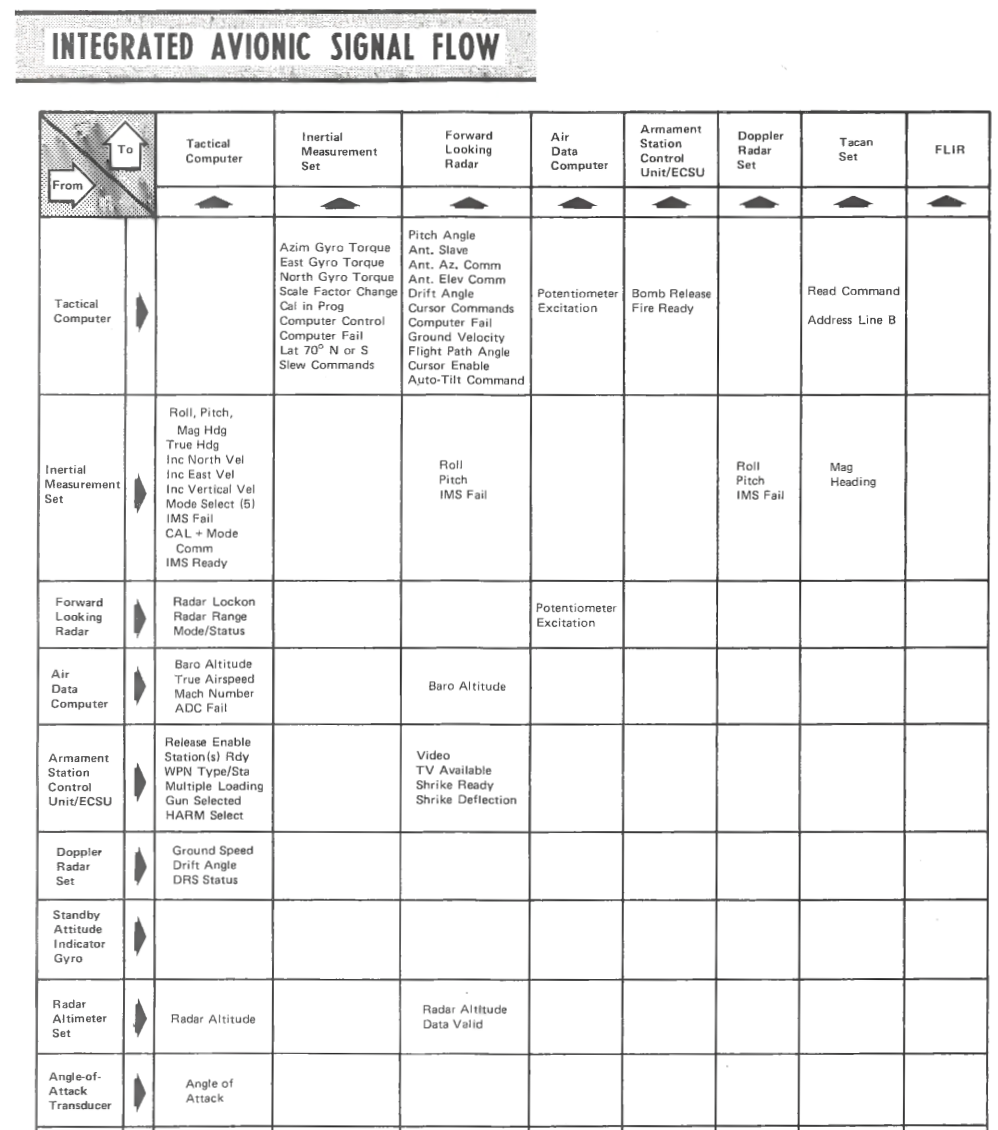
Much time has been spent this year on improving the realism of the flow of information that occurs through the A7's suite of computers and sensors. Every display, every computer, every calculation throughout the avionics suite relies on data that is collected via specific sensors in the aircraft. These sensors pass data through to the AN/ASN-91(V) Tactical Computer, the central brain & processor of the avionics suite. The computer can then run calculations as needed, and feed data to various displays and systems. As you might imagine, any disruptions in this chain of information can have severe consequences on the quality and availability of data available to the pilot.
Fortunately, the NATOPS manual goes into great detail regarding this flow of information & we are also lucky to have access to a paper that extensively details the inner workings of the software used in the avionics suite. You can see an example below, just one page of many demonstrating the flow of information through the aircraft.
To this end, we have been working on detailing our aircraft sensors - the first part of the information chain. We have created an accurate simulation of the Corsairs unique Angle of Attack system, which used non-standard AoA 'units' instead of degrees and is a key data element for a number of display & guidance systems. Work is ongoing to correctly model damage to any sensors, and the consequential disruptions this has on the avionics suite. We are quite pleased with the progress we've made on this front through 2023, having completed the Air Data Computer, begun work on the IMS and have completed integrating most of our systems correctly within the chain of information.
Work has now also begun in earnest on the Tactical Computer, one of the most sophisticated parts of the aircraft (and consequently most complex to develop). The Corsair does not have any modern MFD's; consequently any inputs the pilot needs to make, settings that need to be changed, data that needs to be read - it all happens via the Tactical Computer and its numerical inputs. The functionality of the Tactical Computer is enormous and beyond the scope of this report; however I have included some of the input codes below to give you a taste of how the computer is operated, and the extensive amount of information that can be accessed and edited as required.
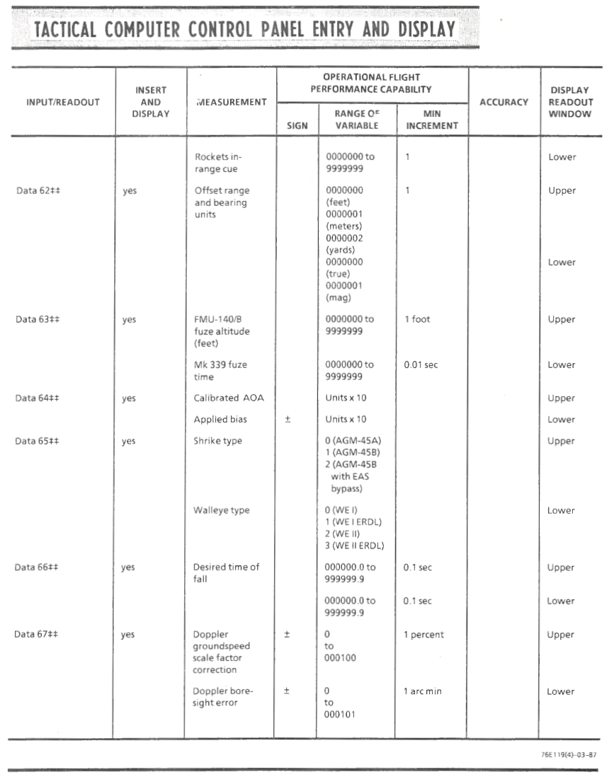
Whilst much of the basic functionality of the Tactical Computer has already been done, we expect we will be continually working on advanced features right up until release.

WHEN WILL IT BE FINISHED??
Two weeks ;)
Just kidding, unfortunately we still don't have a solid estimate on when we will be finished with development. Officially, we are expecting to move into Phase 4 of development sometime early next year, with the aim to begin testing at some point during the year.
We are only a small team, without the resources to really expedite development over a couple of years. What we do have in spades is passion for the aircraft, and a willingness to craft if to the absolute highest standards, as long as that may take. We do want to extend a sincere thank you to everyone reading this, everybody that stops into our discord to chat about the A7 and everybody leaving comments on our social media and blog posts. Truly, you guys have been so patient and supportive of our work, it fills us with pride to be a part of such an excellent community of aviation enthusiasts. Thank you!


Thanks so much for the update. I am so excited for this module. The SLUF is my all time favourite plane.
Excellent update. This is by far my most anticipated of upcoming modules known to be on the slate.
Fantastic work ! Thank you for the Dev update, as I am sure we are all chomping at the bit. This gives the community great satisfaction to see the heart, energy and passion your team is bringing to the project. I cannot wait to support your team and all your hard work vested on its release.
Thank you
Sick update – Awesome work
Great job guys! Can’t wait!
Leave a comment